Listen to audio version of this blog post:
5G's higher frequency bands - especially 3.5 GHz and 26 GHz - have much shorter wavelengths that are blocked by buildings, trees, and walls in ways that 4G's sub-1 GHz signals were not. At these frequencies, signal behavior is dominated by individual building geometry, rooftop diffraction, and direct line-of-sight conditions that 2D clutter maps cannot represent. 3D maps make these physical interactions calculable.
What Made 2D Data "Good Enough" for 4G?
4G LTE deployments were primarily built on 700 MHz, 800 MHz, 1800 MHz, and 2100 MHz frequency bands. At these wavelengths, signals diffract around and through urban environments with relatively predictable behavior. A macro cell at 1800 MHz can serve users behind buildings, around corners, and in basements because the signal bends around obstacles.
2D clutter data - a grid that assigns each pixel a land-use category (urban, suburban, forest, water) - was sufficient because:
- Propagation models like COST-231 Hata were built around these 2D categories
- Macro cell inter-site distances of 500–2000 m meant that fine-grained building geometry mattered less
- Coverage planning focused on outdoor-to-outdoor paths where generalized attenuation coefficients were adequate
The planning philosophy was essentially statistical: categorize the environment broadly, apply empirical loss coefficients per category, and accept that model error would be managed through link budget margins.
Why Does 5G Break the 2D Approach?
Shorter Wavelengths Mean Building Geometry Matters
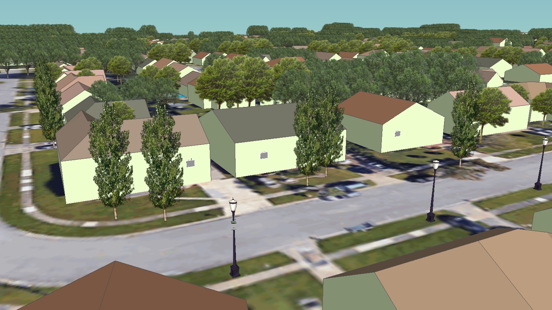
At 3.5 GHz, the wavelength is approximately 8.6 cm. At 26 GHz, it is 1.15 cm. At these scales, the specific geometry of a building - its height, its roofline angle, the distance from street to facade - determines whether a signal diffracts over the top, reflects off a wall, or is blocked entirely.
Two buildings of the same 2D footprint but different heights (say, 12 m vs. 30 m) produce completely different propagation shadows. A 2D map assigns them the same classification. A 3D building model treats them correctly.
Line-of-Sight Becomes the Primary Planning Variable
At mmWave frequencies (26–28 GHz), line-of-sight (LoS) is effectively required for reliable coverage. A 26 GHz signal that passes through a single tree can lose 35.3 dB of power. A signal blocked by a building face loses all useful signal.
LoS analysis requires knowing the 3D height of every obstruction in the propagation path. This is not possible with 2D data.
Small Cell Densification Requires Street-Level Precision
5G sub-6 GHz and mmWave networks require many more sites than 4G - often with inter-site distances of 100–300 m in dense urban areas. At this scale, the difference between a 15 m and a 25 m building in the propagation path is critical. Planning a small cell at street level requires modeling:
- The specific building wall the antenna is mounted on
- Rooftop diffraction from the nearest buildings
- Street canyon effects (signal guided along building facades)
- Reflections off building facades across the street
None of these are modeled accurately with 2D clutter data.
What Specifically Does a 3D Map Provide That 2D Cannot?
| Planning Need | 2D Clutter Data | 3D Building Data |
|---|---|---|
| LoS / NLoS classification | Approximate, statistical | Per-link, deterministic |
| Building diffraction | Average height per class | Exact roofline height |
| Street canyon modeling | Not possible | Direct (wall-to-wall geometry) |
| FWA premises qualification | Not possible | Per-building LoS check |
| Small cell placement | Generalized | Specific candidate surfaces |
| Indoor penetration loss | Generic category | Per-building wall type/depth |
For Fixed Wireless Access (FWA) - one of the most significant 5G business cases - operators must predict which individual residential or commercial premises will receive adequate signal. This is a per-building calculation that requires per-building 3D geometry. A 2D map cannot answer the question "will this specific house at this specific address qualify for 5G FWA service?"
Does This Mean 3D Data Is Required for All 5G Bands?
Not equally. The requirement scales with frequency:
- Sub-1 GHz 5G (700 MHz, 800 MHz): 2D clutter data may still be acceptable for macro coverage planning. Signal behavior is similar to 4G at these bands.
- 3.5 GHz (n78): 3D building data is strongly recommended for urban deployments. Coverage errors of 5–10 dB are common when using 2D clutter only.
- 26 GHz / 28 GHz mmWave: 3D data is mandatory. Propagation at mmWave is essentially optical - if there is no LoS, there is no coverage.
Operators planning 5G NSA (Non-Standalone) using a 4G anchor layer plus 5G NR on 3.5 GHz still need the 3D dataset for the 5G layer, even if the 4G layer continues to run on existing 2D-calibrated models.
How LuxCarta Addresses This
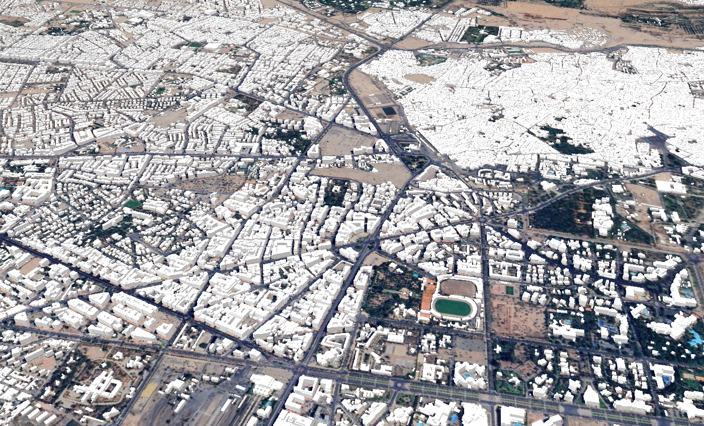
LuxCarta produces LOD1 (building footprint + flat roof height) and LOD2 (building footprint + roof shape geometry) 3D city models from satellite imagery using a U-Net CNN deep learning pipeline. The building extraction achieves a 93%+ capture rate with 87.67% precision and 88.44% recall - validated by customers including Telefónica Deutschland for 26 GHz 5G FWA trials.
Mads Leth-Espensen, Head of Access Network Technology at Telefónica Deutschland, confirmed: "We are happy that LuxCarta has created a geodata solution delivering a close proximity to the environment for real wave propagation at 26 GHz which is actually needed for an accurate modeling of 5G networks."
For operators who need 3D city models outside traditional LiDAR coverage areas, LuxCarta's satellite-based approach delivers consistent global coverage without the cost or scheduling constraints of airborne campaigns. Data is delivered in formats directly compatible with Forsk Atoll, InfoVista Planet (including the AIM propagation model), and TEOCO Asset.
Frequently Asked Questions
Can I use a DSM (Digital Surface Model) instead of 3D building vectors for 5G planning?
A DSM captures the top surface of all objects - buildings, trees, and terrain - as a raster grid. It is a valid alternative to 3D building vectors for sub-6 GHz planning when individual building geometry is not required. However, a DSM at 1–2 m resolution is preferable to one at 5–10 m, and it still cannot match the diffraction-modeling accuracy of explicit LOD1/LOD2 building vectors for mmWave planning.
How much more accurate is 3D propagation modeling compared to 2D?
Studies comparing 2D clutter-based propagation to 3D building-based propagation in urban environments at 3.5 GHz show prediction error improvements of 3–8 dB RMSE. At 26 GHz, the improvement is often larger because LoS/NLoS misclassification in 2D models introduces discrete large errors (the model assumes LoS when the link is actually blocked).
Does 3D geodata affect network planning time?
Yes - processing times increase with more detailed geodata, but modern RF planning tools (Atoll, Planet) are optimized for 3D datasets. The planning accuracy improvement more than offsets the compute overhead by reducing calibration drive testing and the number of physical site visits required.
What is the difference between LOD1 and LOD2 building data?
LOD1 (Level of Detail 1) buildings are represented as box-shaped extrusions - a footprint polygon extruded to a single roof height. LOD2 adds roof geometry (hip roofs, gable roofs, terraces). For RF planning, LOD1 is sufficient for most urban 5G deployments. LOD2 adds value for dense urban mmWave planning where rooftop edge geometry affects diffraction path loss.
Do I need 3D data for rural 5G deployments?
Rural 5G deployments on sub-1 GHz or 3.5 GHz bands can often use DTM plus basic LULC with forested area classification. Where 3D data adds the most value in rural settings is for Fixed Wireless Access at 3.5 GHz or higher, where LoS to individual premises must be verified against tree canopy heights rather than generalized forest classification.
LuxCarta provides high-quality 3D geospatial data solutions for telecom operators worldwide.
Contact our team to access data tailored to the exact resolution requirements of your 5G projects.